LVM Internal Limit Switch Setting
Adjustment dials on the limit switch housing are used to set a motor’s rotational limits. There is one dial for each direction. Each dial moves a cam on the cam wheel closer to or further from its switch (see diagram and arrows). While the motor is running, the cam will travel toward the switch. When it contacts the switch, the motor will stop. Therefore, moving the cam away from the switch will increase the motors rotations/travel in that direction.
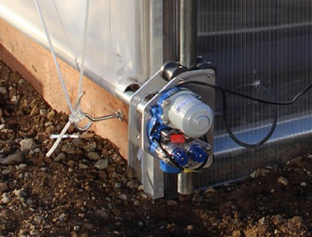
Fig 1
Instructions
1. Attach the motor’s output shaft to the ventilation drive shaft or roll bar.
2. Identify the direction for each dial. The movement of the cam wheels, though very slow, can be observed through the clear plastic limit switch housing. Tip: Powering the motor by touching its wires to the terminals of a portable DC battery (24 V DC or less) can help determine dials/directions as well as set the limits. Reverse rotational direction by reversing wire connections.
3. Loosen set screw at the dial to enable adjustment of that rotation and its function (open or close).
4. The motors are powerful and can cause damage or injury. Assure that the ventilation opening is clear of obstructions.
5. With power to the motor, move the cam a short distance from the switch and towards the opposite dial. The cam will engage the switch after a few rotations. Drive your vent in short intervals this way until the fully open or closed position is reached. Do the same in the opposite direction.
6. Assure that the set screws on both dials are tightened once all limit switch adjustments have been made.
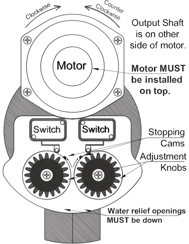
Fig 2: Reversing the motor wires within a junction box, at the controller or at the drill battery terminals, will change rotational direction.