
VCU2-24 Environmental Controller
$1,050.00
| Weight | 14 lbs |
|---|---|
| Dimensions | 12 × 9 × 8 in |
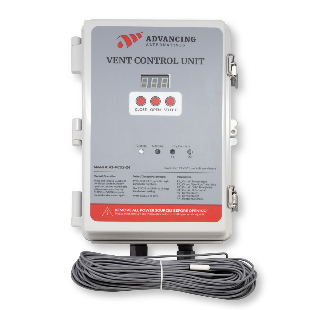
The VCU 2-24 is a single zone environmental controller for greenhouse and high tunnel ventilation, heating and cooling. One unit replaces the separate thermostats normally required for roll-up curtains, heaters and exhaust fans, and coordinates them so they operate as a system rather than independently.
The controller supplies 24VDC power for up to two low voltage curtain motors and provides two dry contacts for heaters, or for fans and louvers through an AC contactor box. All setpoints, run times and differentials are set from a three-button LED interface on the enclosure door.
More than a thermostat
Sensor failure fail-safe. If the temperature sensor fails, the VCU 2-24 does not stop. It falls back to a grower-defined override temperature and continues operating ventilation and heating from that value, while flashing a fault code on the display.
Heater and ventilation interlock. The controller enforces a minimum separation between the ventilation setpoint and the heater setpoint, so the two cannot be programmed into conflict. Without an interlock, a heater set too close to a vent setpoint will run against an open curtain. The interlock band is adjustable up to 20°.
Incremental curtain cycling. Rather than driving curtains fully open on a temperature call, the VCU 2-24 runs the motors for a set number of seconds, idles for a set number of minutes while it continues reading temperature, then either resumes or reverses (or holds steady). Curtains find the position the house actually needs, which prevents the temperature overshoot and cold-shocking that comes from full-travel venting.
High and low temperature alarm output. Independent high and low temperature setpoints drive a dry contact that ties into an existing alarm or autodialer system. Configurable as normally open or normally closed to suit the alarm manufacturer. Frost and overtemperature protection independent of the ventilation logic.
Humidity override with low temperature lockout. With the optional aspirated humidity sensor, the controller vents and runs a fan to pull humidity down for disease control — but stops overriding if the inside temperature drops below a set floor, so humidity management never comes at the cost of chilling the crop.
Fully resettable circuit protection. Every protection device in the unit resets by hand: two circuit breakers, a main fuse, and two motor fuses.
What it controls
Ventilation curtain motors — up to 2, always available. The controller supplies 24VDC power for two low voltage motors on dedicated terminals. These do not use the dry contacts. Both motors operate together on one setpoint.
Two dry contacts — contact #3 and contact #4. These are the only two available outputs, and they are configured as one of the following:
| Configuration | Contact #3 | Contact #4 |
|---|---|---|
| Two heaters | Heater #1 | Heater #2 |
| Two fans / louvers | Fan/louver #1 | Fan/louver #2 |
| One of each | Heater | Fan/louver |
There are two contacts total. Two heaters and two fans is not a supported configuration.
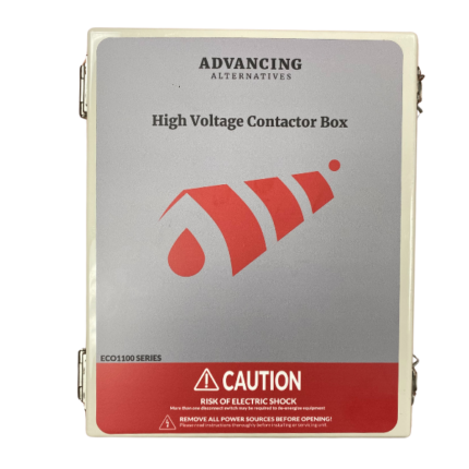
AC fans and louvers require an AC contactor box (42-CB2, ECO-1100, or ECO-1150). Heaters connect directly to the contact with a 24VAC thermostat signal from the heater and are powered independently of the controller.
Temperature alarm output uses contact #4. Enabling the high/low temperature alarm consumes contact #4, leaving contact #3 as the only remaining output. With the alarm enabled, the controller operates one heater or one fan/louver — not two of anything.
| If alarm is… | Available for heat/cool |
|---|---|
| Disabled | Contacts #3 and #4 — two outputs |
| Enabled | Contact #3 only — one output |
Included, required and optional
Included with the controller
- 41-VCU2-24 controller in waterproof, latching enclosure
- 100′ temperature sensor
- Mounting brackets
- User manual
Required, sold separately
- Low voltage curtain motors — LVM60 or LVM100 — if operating ventilation curtains
- AC contactor box — 42-CIBAC-1F1L, 42-CIBAC-2F2L, 42-CB2 or 42-CB4 — if operating fans or louvers
Optional
- Aspirated humidity sensor (46-HUMID) — enables all humidity override functions
- 150′ temperature sensor (46-TS150) — for structures where the included 100′ sensor will not reach
Sensor wire cannot be spliced. Order the 150′ sensor if the run exceeds 100 feet.
Specifications
| Part number | 41-VCU2-24 |
| Series | Vent Control Unit |
| Zones | 1 |
| Input voltage | 110–240 VAC |
| Max amps | 5A |
| Output voltage | 24VDC |
| Output power | 300W |
| Isolation voltage | 5kA |
| Outputs | 4 |
| Setpoints | 3 |
| Inputs | 2 |
| Motor capacity | 2 × 100Nm low voltage motors |
| Enclosure | Waterproof, metal latch, chassis mount |
| Dimensions | 13″ × 9.5″ × 6.5″ |
| Operating temperature | -25°C to 70°C (with derating) |
| Temperature scale | Fahrenheit or Celsius, selectable |
| Circuit protection | 5A breaker, 10A breaker, 10A main fuse, 2 × 5A motor fuses — all resettable |
| Included sensor | 100′ temperature sensor |
Adjustable settings
All settings are entered from the front panel. The following are grower-adjustable:
Ventilation — curtain setpoint, motor run time in seconds, idle time between run cycles, and temperature differential to end the cooling cycle.
Heating and cooling — independent setpoints for each dry contact, plus heater hysteresis / fan differential to control cycling frequency.
Humidity (requires humidity sensor) — curtain override RH%, override run time, fan override RH%, humidity deadspan, and low temperature lockout.
Alarm — independent high and low temperature setpoints, with normally open or normally closed relay state.
Configuration — manual override latch behavior, temperature scale, humidity sensor enable, sensor failure override temperature, alarm relay state, number of heaters, and heater/ventilation interlock band.
Manual override is available at any time from the front panel, with latching or hold-to-run behavior selectable.
Installation
The controller mounts indoors in a dry, protected location using the included brackets. Cable entries must be made in the bottom of the enclosure only — drilling the top or sides voids the warranty.
The temperature sensor mounts at the center of the structure at crop height. Keep sensor wire at least one foot away from high voltage wiring, and cross power lines at 90° rather than running parallel, to avoid inducing erratic readings.
All electrical connections must be made by a qualified, licensed electrician, in accordance with all state and local codes. Heater and fan power supplies connect independently of the controller — never to the controller terminals.
Complete installation, configuration and troubleshooting instructions are in the user manual, available below. Setup guidance is also in our Knowledge Center, and technical support is available at 877.546.2257.
 Prop 65 WARNING: This product can expose you to chemicals known to the State of California to cause cancer, birth defects, or other reproductive harm – p65warnings.ca.gov
1 review for VCU2-24 Environmental Controller
 User Manual
What is the difference between a relay and a contactor?

The difference between a relay and a contactor is the size and power handling capability. A contactor is essentially a large relay. It has heavier contacts and therefore a larger coil. A contactor requires more power to switch and in return can handle heavier loads. In this discussion, the term “relay” will be used to describe both contactors and relays unless otherwise noted. Furthermore, the scope of the discussion is limited to mechanical relays. Solid state relays operate on some of the same principles but are entirely different in construction and application.
Switch configurations
A relay is basically a switch driven by a coil. A review of basic switches is helpful. The most basic switch is the “single pole single throw” (SPST). It simply connects and disconnects one electrical path.
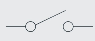
Fig 1: SPST Switch
A second “throw” added to the switch allows the electrical path to be switched to two different destinations, resulting in a “single pole double throw” (SPDT) switch.
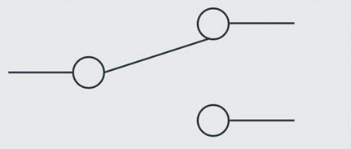
Fig 2: SPDT Switch
A second “pole” can be added, which is essentially a second switchable path identical to the first. The “double pole double throw” (DPDT) is a very common switching configuration for relays used in industrial controls.
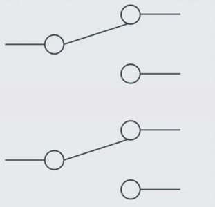
Fig 3: DPDT Switch
A switch is a manually controlled device, such as a toggle switch. A relay is essentially a switch controlled by an electrical signal rather than an external physical operation. Two main purposes of a relay are 1) to control a circuit at a location not local to the control operator and 2) to switch a large signal or power with a small signal. For example, a low power low voltage DC output from an electronic controller could switch a contactor (large relay) that connects high voltage AC power to various devices such as 220 V AC fans. This avoids the necessity for large switching components and the corresponding dangerous high voltage power connections inside the controller box. It also often allows for shorter AC power lines which are far more expensive than a signal wire to a relay.
The schematic representation of a relay consists of a coil and a set of switch contacts. Figure 4 shows a single pole single throw (SPST) relay. The relay is designed and constructed so that when a voltage of proper value is applied to the coil, the coil exerts a magnetic force on the contact mechanism, causing the contacts to touch (make contact) and complete the circuit that is connected to them.
Fig 4: SPST Relay
Figures 5 and 6 are representations of a practical circuit using a relay. In figure 5 the relay contacts are in the “open” (no contact) position, so the AC power circuit to the floodlights is incomplete (“open”). In figure 6 the relay contacts are “closed” (making contact), completing the circuit to the floodlights.
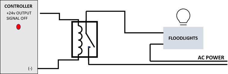
Fig 5: Circuit Using Relay (Open)
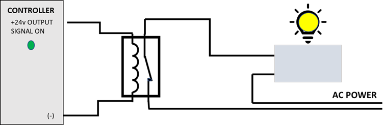
Fig 6: Circuit Using Relay (Closed)
As stated above, two features of the use of the relay are immediately apparent: 1) the controller can be mounted at a location remote from the floodlights and 2) a small signal from the controller can control a much larger amount of electrical power.
Two key specifications of relays are the coil voltage and the power handling of the contacts. Many of the relays used in industrial controls and in Advanced Alternatives products use 24 V DC coils, but it is also common to encounter coils of other voltages, and even some AC coils. Note that AC and DC coils are not compatible. Attempting to drive an AC coil with a DC voltage, or vice versa, will likely result in damage to the relay or the controller. The voltage is also important for proper relay function. Contact ratings must be adequate for the load being switched by the relay.
How many zones does it control?
One. The VCU 2-24 manages a single greenhouse zone, which makes it suited to high tunnels and freestanding houses.
Does it come with the curtain motors?
No. The controller supplies 24VDC power for up to two LVM60 or LVM100 motors, sold separately.
Can I run fans and heaters at the same time?
The two dry contacts can be configured as two heaters, two fans/louvers, or one of each. Fans and louvers require an AC contactor box.
Do I need the humidity sensor?
No — the controller operates on temperature alone. The optional aspirated humidity sensor enables humidity-based overrides for curtains and fans, which is worth adding where disease pressure is a concern.
What happens if the temperature sensor fails?
The controller flashes a fault code and continues operating from a grower-set override temperature until the sensor is replaced. It does not stop controlling.
Can it send an alarm if the house gets too cold?
Yes. Independent high and low temperature setpoints drive a dry contact that connects to an existing external alarm system. The relay can be configured normally open or normally closed.
Is the 100' temperature sensor long enough?
It covers most single-zone structures. Sensor wire cannot be spliced, so if the run exceeds 100 feet, order the 150′ sensor (46-TS150) instead.
Does it require a computer or internet connection?
No. All programming is done from three buttons and an LED display on the enclosure. There is no software and no subscription.
Can it replace my existing heater thermostats?
Yes. The VCU 2-24 is intended to replace existing thermostatic heater controls, sending a 24VAC signal to the heater rather than switching heater power.

Lee –
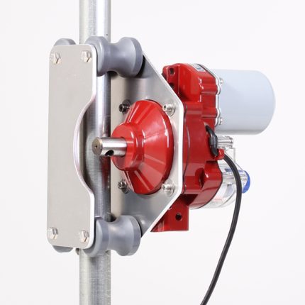
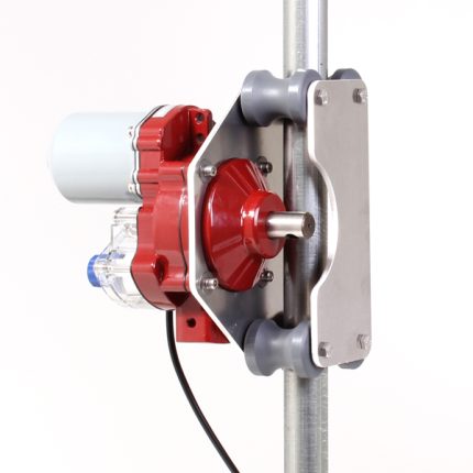
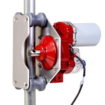
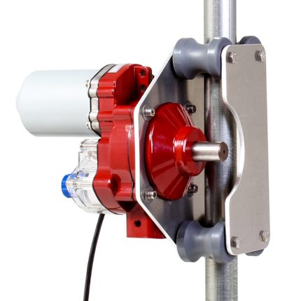
I installed 2 controllers and 3 new motors to replace old controllers and tube motors, these controllers are super easy to setup and install. The motors are light years ahead of the old tube motors. I was going to replace my heater thermostats but decided to use the new controllers instead, great design. I have had them in for 2 years now and Very happy!