Understanding and Application of Contactors and Relays
The difference between a relay and a contactor is the size and power handling capability. A contactor is essentially a large relay. It has heavier contacts and therefore a larger coil. A contactor requires more power to switch and in return can handle heavier loads. In this discussion, the term “relay” will be used to describe both contactors and relays unless otherwise noted. Furthermore, the scope of the discussion is limited to mechanical relays. Solid state relays operate on some of the same principles but are entirely different in construction and application.
Switch configurations
A relay is basically a switch driven by a coil. A review of basic switches is helpful. The most basic switch is the “single pole single throw” (SPST). It simply connects and disconnects one electrical path.
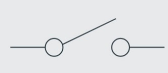
Fig 1: SPST Switch
A second “throw” added to the switch allows the electrical path to be switched to two different destinations, resulting in a “single pole double throw” (SPDT) switch.
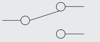
Fig 2: SPDT Switch
A second “pole” can be added, which is essentially a second switchable path identical to the first. The “double pole double throw” (DPDT) is a very common switching configuration for relays used in industrial controls.
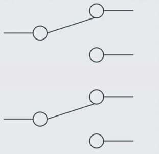
Fig 3: DPDT Switch
A switch is a manually controlled device, such as a toggle switch. A relay is essentially a switch controlled by an electrical signal rather than an external physical operation. Two main purposes of a relay are 1) to control a circuit at a location not local to the control operator and 2) to switch a large signal or power with a small signal. For example, a low power low voltage DC output from an electronic controller could switch a contactor (large relay) that connects high voltage AC power to various devices such as 220 V AC fans. This avoids the necessity for large switching components and the corresponding dangerous high voltage power connections inside the controller box. It also often allows for shorter AC power lines which are far more expensive than a signal wire to a relay.
The schematic representation of a relay consists of a coil and a set of switch contacts. Figure 4 shows a single pole single throw (SPST) relay. The relay is designed and constructed so that when a voltage of proper value is applied to the coil, the coil exerts a magnetic force on the contact mechanism, causing the contacts to touch (make contact) and complete the circuit that is connected to them.

Fig 4: SPST Relay
Figures 5 and 6 are representations of a practical circuit using a relay. In figure 5 the relay contacts are in the “open” (no contact) position, so the AC power circuit to the floodlights is incomplete (“open”). In figure 6 the relay contacts are “closed” (making contact), completing the circuit to the floodlights.
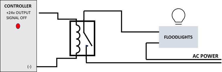
Fig 5: Circuit Using Relay (Open)
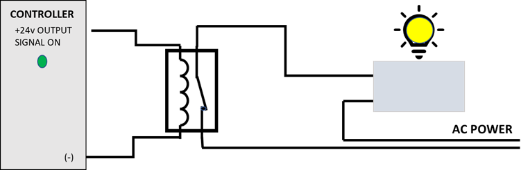
Fig 6: Circuit Using Relay (Closed)
As stated above, two features of the use of the relay are immediately apparent: 1) the controller can be mounted at a location remote from the floodlights and 2) a small signal from the controller can control a much larger amount of electrical power.
Two key specifications of relays are the coil voltage and the power handling of the contacts. Many of the relays used in industrial controls and in Advanced Alternatives products use 24 V DC coils, but it is also common to encounter coils of other voltages, and even some AC coils. Note that AC and DC coils are not compatible. Attempting to drive an AC coil with a DC voltage, or vice versa, will likely result in damage to the relay or the controller. The voltage is also important for proper relay function. Contact ratings must be adequate for the load being switched by the relay.