External Limit Switch Assembly for Rack & Pinion Low Voltage Motors (LSARL-LVM-RP)
Installation Instructions

Read completely through these instructions before beginning your installation to familiarize yourself and compare what you received with the instructions.

Always wear eye and ear protection. Always use gloves and other necessary safety equipment. Metal can be sharp, handle carefully to avoid injury.
Qualified electricians should provide any electrical installation.
Components Included
1 – Lever Style Limit Switch with 8’ of wire
2 – Aluminum Mounting Plate
4 – 1/4”x 1” Stainless Steel Bolts
4 – 1/4” Stainless Steel Nuts
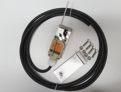
Fig 1: Components
Instructions
An external limit switch is needed when using a Low Voltage Motor for your Rack & Pinion. These instructions will guide you through the installation process. Since there are many different Rack & Pinion manufacturers and greenhouses, we have tried to generalize the instructions to fit every style and type of system.
1. First you will want to mount your Low Voltage Motor to a greenhouse bow or a mounting bracket that may have been constructed by your greenhouse installer. Instructions for the Low Voltage Motor are found with the motor package.
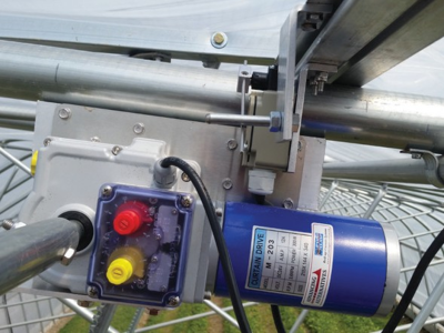
Fig 2
2. The second process is to mount the limit switch. This is the gray box mounted to an “L” bracket. Mount the limit switch near the motor so that the 8’ limit switch wire will reach the motor. A vice grip or “C” clamp is a nice addition to help with the installation of these parts. Clamp the “L” bracket with the limit switch to the stationary portion and drill two ¼” holes through the aluminum. After the holes are drilled you will use the ¼” bolts and nuts to fasten the bracket to your Rack & Pinion vent header or sill. You will want the limit switch as close to the edge of the sill as possible. See figure 3 for a visual reference.
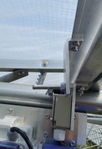
Fig 3
3. The third step is to mount the trigger pin. This is the 3/8” pin that will hit the limit switch, killing the power to the motor. You will mount this part to the moving portion of the Rack & Pinion. As before, clamp it to the bottom sash and drill two ¼” holes through the sash. Attach the trigger “L” bracket to the bottom sash with the 1/4” bolts and nuts.
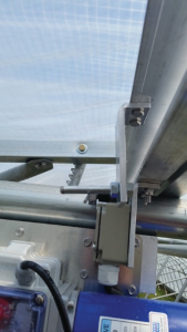
Fig 4a
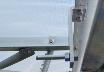
Fig 4b
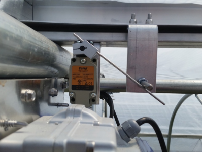
Fig 5
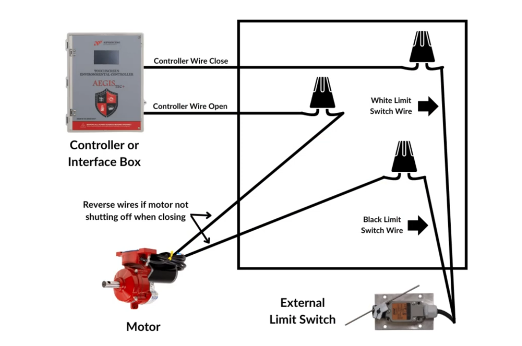
4. After mounting all the hardware you will wire the limit switch in tandem with the Low Voltage Motor. The 8’ wire provided with the limit switch should be more than sufficient to reach your motor.
5. Wire the limit switch. Connect the wires as follows:
- Black wire from limit switch → connects to one motor wire (Motor Wire A)
- White wire from limit switch → connects to Controller CLOSE wire
- Controller OPEN wire → connects to the other motor wire (Motor Wire B)
Troubleshooting: If the motor is not shutting off when closing, swap the two motor wires:
Motor Wire B (previously connected to black limit switch wire) → now connects to Controller OPEN
Motor Wire A (previously connected to Controller OPEN) → now connects to black limit switch wire
Always remember to perform routine maintenance checks on all your equipment, especially at the beginning and end of each season!