Selecting the Appropriate Wire Size for 24V DC Motor Systems in Greenhouse Automation: Mitigating Voltage Drop in Long Runs
Introduction
At Advancing Alternatives, we specialize in greenhouse automation solutions, including control enclosures equipped with DC power supplies to power our 24V DC motors, such as those in the LVM series used for curtain and vent systems. Our power supplies deliver slightly higher output voltages—typically 25V to 30V depending on the model, to account for transmission losses and ensure reliable performance.
This elevated source voltage provides headroom for the 24V DC motors, which should be operated at voltages between 22 and 28V DC. Variations within this range are perfectly acceptable. The motor speed and load capacity will vary slightly but not significantly in most cases.
A common customer inquiry concerns wire sizing from the control enclosure to the motor, as voltage drop over long runs can impact performance. Excessive drop may result in reduced torque, slower operation, overheating, or startup failures, particularly in greenhouse environments where motors drive large curtains or vents.
Our general rule of thumb for multi-strand copper wire is: 14 AWG for runs under 100 feet, 12 AWG for 100-200 feet, 10 AWG for 200-300 feet, and avoid exceeding 300 feet to prevent unacceptable losses or interference. For a more accurate calculation and an optimal installation, this article explains voltage drop principles, calculation methods, and our guidelines tailored for Advancing Alternatives’ systems.
Understanding Voltage Drop in DC Circuits
Voltage drop is the reduction in voltage along the conductor due to resistance, governed by Ohm’s Law: V=I X R (V=voltage I=current, R= resistance) or Volts = Amps X Ohms). For a two-wire DC motor connection, the length is doubled, since the current flows through both wires and the total voltage drop is the sum of the drop in each wire.
Example calculation
Assume that we have a motor that will draw 5A (note that the motor current is dependent on the size of the curtain or vent). The distance of the wire connection is 100 feet. We want to keep the operating voltage of the motor close to 24V. A generally acceptable range is 22-28V.
Wire resistance for different gauge wire is as follows, in ohms per foot:
12 ga .0016 Ω
14 ga .0025 Ω
To determine total resistance, multiply the resistance in ohms (Ω) per foot by 200, accounting for the two wires. This results in:
12 ga .32 Ω
14 ga .5 Ω
Note that wire is normally specified in ohms per 1000ft.; simply divide by 1000 to get ohms per foot.
Now, to determine how much voltage will be lost in the wires (voltage drop), multiply the current (5A) by the total resistance in ohms, to get the following result for each of the three gauges of wire:
A 10 ga 1.0 V
12 ga 1.6 V
14 ga 2.5 V
It can be seen from this example that for the conditions assumed, 14 ga wire is sufficient; a 25V supply will deliver 22.5V (25 – 2.5) to the motor.
The voltage drop multiplies linearly for longer or shorter runs. For example, for a 200 foot run, the voltage drops calculated above can simply be doubled, for the following results:
B 10 ga 2.0 V
12 ga 3.2 V
14 ga 5 V
In this case it is evident that 14 ga wire is insufficient, producing a drop of 5V. 12 ga would be a better choice, of for best performance 10 ga could be used.
Likewise, the numbers can scaled for different motor currents. For example, if the expected motor current is 5A and the run is 100 feet, multiplying the A results by 8/5 (8 amps over 5 amps), or 1.6, gives the following:
C 10 ga 1.6 V
12 ga 2.56 V
14 ga 4 V
For our 24V DC motors (5A typical), use multi-strand copper wire per these guidelines to keep drop under ~4V (from 28V source):
- Under 100 feet: 14 AWG
- 100-200 feet: 12 AWG
- 200-300 feet: 10 AWG
- Over 300 feet: Not recommended—relocate the enclosure, use higher-voltage transmission, or opt for local controls.
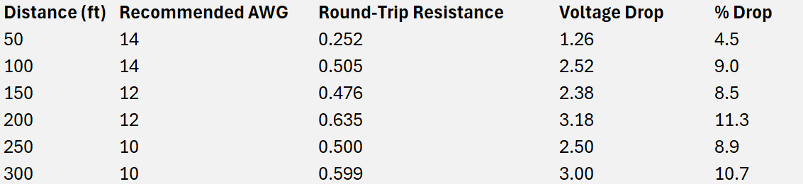
The table below shows calculated drops at 5A and 28V source, confirming the guidelines maintain motor voltage around 25-27V at maximum lengths:
In some applications with large vents and large motors, the motor startup current can be a factor. This varies greatly from one installation to another, and is not usually a problem; however in heavy duty applications it is good to err or the side or larger wire to avoid the possibility of startup problems.
Additional Considerations for Greenhouse Applications
- Safety and Compliance: 24V DC is low-voltage (NEC Class 2), but use UL-listed wire suitable for damp environments. Fuse the output for protection.
- Alternatives for Extended Runs: For distances over 300 feet, consider AC power to our ECO or AegisTEC+ controllers.
- Motor-Specific Notes: Our LVM motors (e.g., LVM100 at ~4.2A full load) align with the 5A typical; consult specs for your model.
Following these guidelines ensures reliable greenhouse automation with Advancing Alternatives’ systems. For custom setups or higher-current models, contact us at www.advancingalternatives.com for tailored advice.